
Contents:
Some Intro Info
Basic Conversion Rules
EXAMPLE (converting the previous ERD diagram with weak ET)
Converting Optional 1-M Relationships
Converting Generalization Hierarchies
Converting 1-1 Relationships
THE WHOLE ERD SAMPLE FOR THE PREVIOUS EXAMPLE
Water Utility ERD With A Generalization Hierarchy Example
Converting the ERD to Relational Model (MySQL) - This is an optional part
Enhanced Entity Relationship – Another Exercise
Converting ERD Model to Relational Model (MySQL) - This is an optional part
Reverse Engineer the Relational Model Back to ERD Using DBDesigner
Some Intro Info
The SQL script used are generic SQL 2003 standard otherwise mentioned. The rules related thingy was taken and analyze from Mannino text book to grasp the idea. There are 7 rules regarding the ERD to relational model. Every rule specific to the related relationship type (1-M, M-M, etc….). The acronyms used in this tutorial: PK – Primary Key, FK – Foreign key, ET – Entity Type.
Basic Conversion Rules
The basic rules convert everything on the ERD except generalization hierarchies. You should apply these rules until everything on an ERD is converted except for generalization hierarchies. You should use the first 2 rules before the other rules. As you apply these rules, you can use a check mark to indicate the converted parts of an ERD.
- Entity Type Rule: Each entity type (except subtypes) becomes a table. The PK of ET (if not weak) becomes the PK of the table. The attributes of the ET become columns in the table. This rule should be used first before the relationship rules.
- 1-M Relationship Rule: Each 1-M relationship becomes a FK in the table corresponding to the child type (the entity type near Crow’s Foot symbol). If the minimum cardinality on the parent side of the relationship is one, the FK cannot accept null values (NOT NULL must be used).
- M-N Relationship Rule: Each M-N relationship becomes a separate table. The PK of the table is a combined key consisting of the primary keys of the entity types participating in the M-N relationship.
- Identification Dependency Rule: Each identifying relationship (denoted by a solid relationship line) adds a component to a PK. The PK of the table corresponding to the weak entity consists of:

CREATE TABLE Course(
CourseNo CHAR(6),
CrsDesc VARCHAR(30),
CrsUnits SMALLINT,
CONSTRAINT PKCourse PRIMARY KEY (CourseNo)
);
CREATE TABLE Offering(
OfferNo INTEGER,
OffLocation CHAR(20),
CourseNo CHAR(6) NOT NULL,
OffTime TIMESTAMP,
...
CONSTRAINT PKOffering PRIMARY KEY (OfferNo),
CONSTRAINT FKCourseNo FOREIGN KEY (CourseNo) REFERENCES Course
);
Converting the generic SQL script to tables we have the following:
Rule 1 is applied to convert the Course and Offering ETs to tables. Then, Rule 2 is applied to convert the Has relationship to a FK (Offering.CourseNo). The Offering table contains the FK because the Offering ET is the child ET in the Has relationship. The minimum cardinality on the parent side of the relationship is one, the FK cannot accept null values (that is why the NOT NULL being used).
| |||||||||||||||||||||||||||
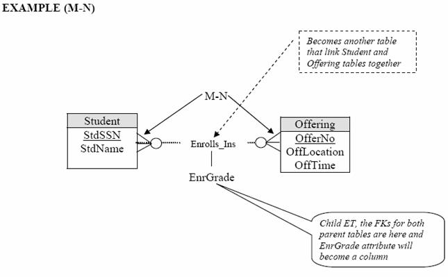
Using Rule 3 leads to the extra Enrolls_in table. The PK of Enrolls_In is a combination of the PKs of the Student and Offering ETs.
CREATE TABLE Student(StdSSN CHAR(11),StdName VARCHAR(30),...CONSTRAINT PKStudent PRIMARY KEY (StdSSN));CREATE TABLE Offering(OfferNo INTEGER,OffLocation VARCHAR(30),OffTime TIMESTAMP,...CONSTRAINT PKOffering PRIMARY KEY (OfferNo));CREATE TABLE Enrolls_In(OfferNo INTEGER,StdSSN CHAR(11),EnrGrade DECIMAL(2,1),CONSTRAINT PKEnrolls_In PRIMARY KEY (OfferNo, StdSSN),CONSTRAINT FKOfferNo FOREIGN KEY (OfferNo) REFERENCES Offering,CONSTRAINT FKStdSSN FOREIGN KEY (StdSSN) REFERENCES Student);
Converting the generic SQL script to tables we have the following:

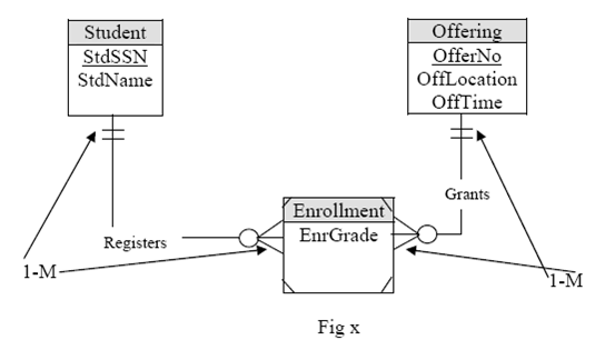
For Rule 4, the identification dependency can be used to convert the ERD in the following figure. The result of converting the previous figure is identical to the following figure except that the Enrolls_In table is renamed Enrollment. The following figure requires 2 applications of the identification dependency rule. Each application of the identification dependency rule adds a component to the PK of the Enrollment table. So M-N becomes two 1-M relationships.
EXAMPLE (converting the previous ERD diagram with weak ET)
In the following Figure, both sides will become 1-M relationship.
Converting the generic SQL script to tables we have the following tables:
Student
| ||
StdSSN (PK)
|
StdName
|
...
|
...
|
...
|
...
|
Offering
| ||||
OfferNo (PK)
|
OffLocation
|
CourseNo (FK)
|
OffTime
|
...
|
...
|
...
|
...
|
...
|
...
|
Enrollment
| ||||
OfferNo (PK + FK)
|
StdSSN (PK + FK)
|
EnrGrade
|
...
|
...
|
...
|
...
|
...
|
...
|
...
|
The rules also can be used to convert self-referencing relationships as shown in the following figures.

Using 1-M relationship rule, the Supervises relationship converts to a FK in the Faculty table as shown in the following SQL script.
CREATE TABLE Faculty(FacSSN CHAR(11),FacName VARCHAR(30),FacSupervisor CHAR(11),...CONSTRAINT PKFaculty PRIMARY KEY (FacSSN),CONSTRAINT FKSupervisor FOREIGN KEY (FacSupervisor) REFERENCES Faculty);
Converting the generic SQL script to tables we have the following:
Faculty
| ||||
FacSSN (PK)
|
FacName
|
FacSupervisor (FK to the same table)
|
...
|
...
|
...
|
...
|
...
|
...
|
...
|

Using M-N relationship rule, the Prereq_To relationship converts to the Prereq_To table with a combined PK of the course number of the prerequisite course and the course number of the dependent course.
CREATE TABLE Course(CourseNo CHAR(6),CrsDesc VARCHAR(30),CrsUnits SMALLINT,CONSTRAINT PKCourse PRIMARY KEY (CourseNo));CREATE TABLE Prereq_To(PrereqCNo CHAR(6),DependCNo CHAR(6),CONSTRAINT PKPrereq_To PRIMARY KEY (PrereqCNo, DependCNo),CONSTRAINT FKPrereqCNo FOREIGN KEY (PrereqCNo) REFERENCES Course,CONSTRAINT FKDependCNo FOREIGN KEY (DependCNo) REFERENCES Course);
So the M-N becomes 1-M relationships. Converting the generic SQL script to tables we have the following:
Course
| |||
CourseNo (PK)
|
CrsDesc
|
CrsUnits
|
...
|
...
|
...
|
...
|
...
|
Prereq_To
| |||
PrereqCNo (PK + FK)
|
DependCNo (PK + FK)
|
...
|
...
|
...
|
...
|
...
|
...
|
The following example shows conversion rules applied to more complex identification dependencies.

The first part of the conversion is identical to the conversion of the previous one (Fig x). Application of the 1-M rule makes the combination of StdSSN and OfferNo FKs in the Attendance table as shown in the following SQL script. Note that the FKs in Attendance refer to Enrollment, not to Student and Offering. Finally, one application of the identification dependency rule makes the combination of StdSSN, OfferNo and AttDate the PK of the Attendance table.
CREATE TABLE Attendance(OfferNo INTEGER,StdSSN CHAR(11),AttDate DATE,Present BOOLEAN,CONSTRAINT PKAttendance PRIMARY KEY (OfferNo, StdSSN, AttDate),CONSTRAINT FKOfferNoStdSSN FOREIGN KEY (OfferNo, StdSSN) REFERENCES Enrollment);
Converting the generic SQL script to tables we have the following:
Attendance
| |||
OfferNo (PK + FK)
|
StdSSN (PK + FK)
|
AttDate (PK)
|
Present
|
...
|
...
|
...
|
...
|
Converting Optional 1-M Relationships
When you use the 1-M relationship rule for optional relationships, the resulting FK may contain NULL values. Recall that a relationship with a minimum cardinality of 0 is optional. For example the Teaches relationship in the following figure is optional to Offering because an Offering ET can be stored without being related to a Faculty ET. Converting the following figure results in two tables (Faculty and Offering) as well as a FK (FacSSN) in the Offering table.

The FK should allow NULL values because the minimum cardinality of the Offering ET in the relationship is optional (may be or can be 0). However, NULL values can lead to complications in evaluating the query results. To avoid NULL values when converting an optional 1-M relationship, you can apply Rule 5 to convert an optional 1-M relationship into a table instead of a FK. The following SQL script shows an application of Rule 5 to the ERD of the previous figure. The Teaches table contains the FKs OfferNo and FacSSN with NULL values not allowed for both columns. In addition the Offering table no longer has a FK referring to the Faculty table.
CREATE TABLE Faculty(FacSSN CHAR(11),FacName VARCHAR(30),...CONSTRAINT PKFaculty PRIMARY KEY (FacSSN));CREATE Offering(OfferNo INTEGER,OffLocation VARCHAR(30),OffTime TIMESTAMP,...CONSTRAINT PKOffering PRIMARY KEY (OfferNo));CREATE TABLE Teaches(OfferNo INTEGER,FacSSN CHAR(11) NOT NULL,-- The PK used is from childCONSTRAINT PKTeaches PRIMARY KEY (OfferNo),CONSTRAINT FKFacSSN FOREIGN KEY (FacSSN) REFERENCES Faculty,CONSTRAINT FKOfferNo FOREIGN KEY (OfferNo) REFERENCES Offering);
Converting the generic SQL script to tables we have the following:
Faculty
| ||
FacSSN (PK)
|
FacName
|
...
|
...
|
...
|
...
|
Offering
| |||
OfferNo (PK)
|
OffLocation
|
OffTime
|
...
|
...
|
...
|
...
|
...
|
Teaches
| ||
OfferNo (PK + FK)
|
FacSSN (FK)
|
...
|
...
|
NOT NULL
|
...
|
The following is another example converting 1-M relationship with an attribute. Note that the Lists table contains the Commission column.
EXAMPLE
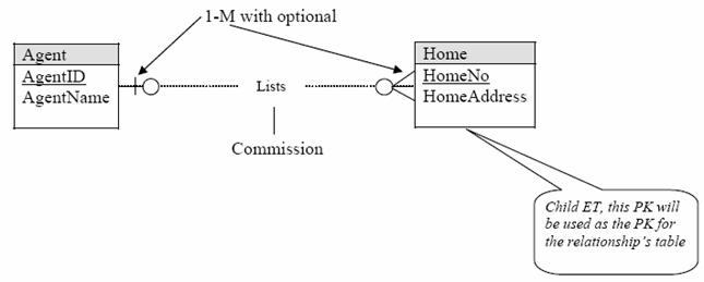
CREATE TABLE Agent(AgentId CHAR(10),AgentName VARCHAR(30),...CONSTRAINT PKAgent PRIMARY KEY (AgentId));CREATE TABLE Home(HomeNo INTEGER,HomeAddress VARCHAR(50),...CONSTRAINT PKHome PRIMARY KEY (HomeNo));CREATE TABLE Lists(-- NOT NULL is not used because it is PK for the table-- and it is already NOT NULLHomeNo INTEGER,-- Must put NOT NULLAgentId CHAR(10) NOT NULL,Commission DECIMAL(10,2),-- The PK used is from childCONSTRAINT PKLists PRIMARY KEY (HomeNo),CONSTRAINT FKAgentId FOREIGN KEY (AgentId) REFERENCES Agent,CONSTRAINT FKHomeNo FOREIGN KEY (HomeNo) REFERENCES Home);
Converting the generic SQL script to tables we have the following:
Agent
| ||
AgentId (PK)
|
AgentName
|
...
|
...
|
...
|
...
|
Home
| ||
HomeNo (PK)
|
HomeAddress
|
...
|
...
|
...
|
...
|
List
| ||
HomeNo (PK + FK)
|
AgentId (FK)
|
Commission
|
...
|
NOT NULL
|
...
|
Then, from the previous example we have the fifth rule:
5. Optional 1-M relationship Rule: Each 1-M relationship with 0 for the minimum cardinality on the parent side becomes a new table. The PK of the new table is the PK of the ET on the child (many) side of the relationship. The new table contains FKs for the PKs of both ETs participating in the relationship. Both FKs in the new table do not permit NULL values. The new table also contains the attributes of the optional 1-M relationship as in the previous example, a Commission.
Rule 5 is controversial. Using Rule 5 in place of Rule 2 (1-M Relationship Rule) avoids NULL values in FKs. However, the use of Rule 5 results in more tables. Query formulation can be more difficult with additional tables. In addition, query execution can be slower due to extra joins. The choice of using Rule 5 in place of Rule 2 depends on the importance of avoiding NULL values versus avoiding extra tables. In many database, avoiding extra tables may be more important than avoiding NULL values. We will continue on next part 2.
The following are useful notes and tutorials on ERD, Normalization and database modeling in PDF format:


